Opening the Laser 3000


Image: Unpunctured Seal

Image: Punctured Seal

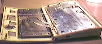
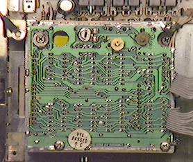
I finally punctured the warranty seal on the bottom of the Laser 3000 on May 28th, 1998. It had actually been removed from the machine earlier, after the machine had died because of a bad solder joint in the power supply (I zapped myself playing with that!). The warranty seal was carefully peeled back with a knife, and put back on after the operation. The top photograph shows what it looked like after that had been done. I decided to quit the pretense and puncture the thing this time. Besides, it hardly survived "undamaged" from the first peeling.

This is what the L3K looks like when the screws in the case have been removed and it's been opened up like a clam shell. There are three cables attaching the top and bottom portions, two of which lead to the keyboard. The other one goes to the internal speaker, which is mounted above the keyboard.

As you can see, the machine is well shielded.

Image: L3K With The Top Flipped Off
Image: Laser 3000 Motherboard

Beneath the glare in this photo is the L3K motherboard. It has been completely removed from the machine.

The 30-pin edge connector at the top left is the "RS-232 Interface". The big edge connector in the middle is the "System Bus". The small edge connector at the right corner is the "Printer" port.

On the right side, is an unlabled female edge connector that is normally hidden by a plastic cover. This is where the FP BASIC cartidge plugs in, and I suspect that the CP/M cartridge goes there as well. Most of its pins are connected directly to pins of the system bus connector. An internal connector (seen as two vertical white strips) is also connected to this bus. That is where my L3K's daughterboard lives.

The protruding black connector at the bottom of the right hand side is the joystick connector. At bottom, near the right (barely visible) are the pins of the keyboard connector.

Many chips are unidentifiable because they've got metal plates soldered to their tops. I didn't feel like taking the risk of removing the plates. Some other chips have stickers on them which I also didn't remove.

The shiny object at the bottom left-hand side of the image is the plate that covers the eight RAM chips. Many of the chips get no benefit from this as they don't make contact with the plate. The other metal plate, with the big daub of solder on it, probably covers the CPU. I haven't bothered to compare the chip with a 6502.

Image: Chips Covered With Metal Plates
Image: Large IC On The Motherboard

Aha! Here's one major component that can be identified. I haven't yet bothered to find out what this part does, but it's a 64-pin chip from Toshiba with a part number "TC15G014AP". I'll have to ask around, to see if it's a standard component.

That's the motherboard's power connector at the upper left corner.

This is the underside of the daughterboard. I don't know what function the board has. This board sits on the internal system bus connector. Two of the chips are RAM (4416), the rest are TTL. The machine operates properly, including all graphics modes, without this board in place. However, when I reassembled the L3K the normal Apple hi-res modes didn't function correctly until this board was re-seated. (HGR3, 4, 5, and 6 seemed to be fully functional.)

Notice that there is space for another connector on the end opposite the system bus connector.

Image: L3K Daughterboard
Image: Resistors Covered In Glue

This is really sad, but it's a fact of the Laser 3000. A lot of things are held in place or insulated with hot glue. It's not really a bad idea, but to me this doesn't say "quality".

The two video ports, the cassette port, and the sound volume knob all connect directly to this piece of circuitry. This is actually the top of a "circuit sandwich" of two printed circuit boards with lots of components between them. There's all kinds of little adjustment thingies on this thing, too. (Don't you just love all of my technical terms?)

Those little prongs coming out the side of the "sandwich" at the bottom of the picture connect to the computer's speaker.

Image: Video & Cassette Module

[Laser 3000 Home] [Hrothgar's Cool Old Junk Page] 1998-10-31